VIPER Angle Encoding System
Purpose:
To accurately read an angle encoding device that can be fixed to the 2-m Radio Telescope. Using MATLAB Simulink, an arduino microcontroller and a Keyes KY-040 Rotary Encoder module to determine the elevation angle, in both the laboratory and field settings. Additionally, establish a procedure for operation of the model in both settings.Background:
Accurately pointing the 2-m Radio Telescope is the most important function of VIPER's controlling system. To do so an Incremental Rotary Encoder is being implemented to read changes in the current angle of the telescope. To familiarize yourself with an Incremental Rotary Encoder click here and for Gray Coding click here; this device is currently being used on the VIPER Radio Telescope. The arduino code from the above link is not a precise code, as its purpose is to introduce the user to the encoder.What This Blog Accomplishes:
A explanation of how this model works, including the MATLAB Function, and how to use it in both the laboratory and field setting.
 |
| Using MATLAB Simulink, a microcontroller, and an Incremental Rotary Encoder angle changes can be detected and recorded. To do so two inputs are required to detect these changes (the CLK and DT of the encoder). With these two inputs and the application of the proper Simulink functions a precise angle encoder can be modeled and implemented. |
Simulinks Blocks Used:
 |
| Simulink Display Block |
 |
| Simulink Memory Block |
 |
| Simulink Detect Change Block |
 |
| Simulink MATLAB fcn Block |
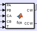
The MATLAB Function block connects the running Simulink model to a MATLAB .m script. This happens to be the brains of the operation as it compares values and determines their output. The inputs of this particular block are: PAST A 'PA', PAST B 'PB', CURRENT A 'CA', CURRENT B 'CB', and TRIGGER 'T', and the outputs: Clockwise 'CW' and Counter-Clockwise 'CCW' boolean values.
 |
| Simulink Counter Block Reset (RST) is an optional feature, it is not necesary. |
 |
| To determine the value of the gain multiple the number of clicks per revolution by 4, this is your denominator. This encoder had 20 clicks, therefore 80. Divide 360 by this number for the angle of each increment. |
MATLAB Function Block:
 |
| Above is the working code to determine the direction of the spin. Note: This is an image for a reason, so you can't copy and paste the code into your own. You will have to type it onto your IDE, this will help you understand the gray coding further. The name of the function 'fcn' can be changed at any point within this editor, so, if you deleted it and replaced 'fcn' with 'Angle Encoder' the later will appear in your simulink block as soon as you save the project, if it hasn't updated itself. I left the code in terms of default settings. The code begins on LINE 1 with ' function [...] ' |
fcn step by step:
| Initial MATLAB script when a new function is created from Simulink. Not found in working code. |
 |
| Working .m code initialization lines. LINES 1-2 |
Initialization of this code is important. Simulink will start you off automatically with a blank function template (left image), begin to type your code underneath the %#codegen line. To change the output variables enter the variable name to the left of the '=' in the first line (right image).
Declaring that the variables CW and CCW have the value of Not a Number 'NaN' allows for this code to run smoothly when there are no changes in the values of PA to CA or PB to CB. You may also write them to hold the value of '0'. For debugging purposes the working code wrote them as 'NaN' so that when testing of the encoder was in progress a change was noticeable on the respective displays.
 |
| Initial conditions of the working model. NaN stands for Not a Number which is simply a blank placeholder. LINES 5-6 |
 |
| Trigger 'T' condition statement. LINE 8 |
Once the value of T is that of '1' the code runs to the first set of if statements that will determine the direction of motion. These if statements are based off of the GRAY CODING mentioned in the background.
Clockwise (CW)
|
Counter-Clockwise (CCW)
|
0001
|
0010
|
0111
|
0100
|
1110
|
1101
|
1000
|
1011
|
The if statements are based on these four (4) rows of code. Each row has the same first two (2) bit values but the second two (2) bits are different, allowing for the .m code to distinguish the direction.
To avoid senseless repetition a single run through of LINES 8-17 will be explained, the rest of the LINES are similar but tweaked to fulfill the other 6 cases.
 LINE 8: If there is a change read PA
LINE 9: If PA is equal to 0 proceed
LINE 10: If PB is equal to 0 proceed
LINE 11: If CA is equal to 0 and CB is equal to 1 THEN Clockwise is true. Similarly,
LINE 14: If LINE 11 isn't true see if CA is equal to 1 and CB is equal to 0 THEN Counter-Clockwise is TRUE.
The same idea is followed for the rest of the code keeping the chart's row relationship as the foundation of the statements.
 |
| END all processes in MATLAB code |
Note: MATLAB R2016a was used.
Raw MATLAB .m Code OUTPUT (for DEBUGGING and LEARNING)
If you were to run the .m code in another script, so that only MATLAB is being run, the outputs will be identical to the following two (2) figures. To write such a code the 'arduino' support package must be installed in MATLAB, to install type "arduino" into the command window and follow the prompts.
 |
| Altered .m Code for MATLAB usage. Make sure to replace the 'if (T==1)' LINE with the a while (1==1) loop so that the code will always run. |
After the arduino support package is installed copy the fcn code, but, alter the first few lines so that the arduino will connect (see above image). The first if statement after the readDigitalPin commands serve as the triggers. if ( PA~=CA || PA~=CA ) '~=' means to not be equal to, it is the same as '!=' in C++ and the '||' is an or statement. This allows either condition to let the script run. To update the Current Pin state simply read in those values before the comparison explained previously. To finalize the conversion to a MATLAB script before the while loop is closed the Past Values must be redefined from the current values. This is so that reading the arduino is minimized.
 |
| Counter-Clockwise TRUE |
 |
| Clockwise TRUE Motion |
Connecting the Arduino Microcontroller to MATLAB
To connect any arduino to MATLAB you first must INSTALL the support package for Arduino Microcontrollers. To do this type 'arduino' into the Command Window of MATLAB and allow MATLAB to run the installation process. After this is completed restart MATLAB.
With the support package installed type 'arduino' into the command window again to connect. If you have a GENUINE Arduino all you have to do is type 'arduino' into the Command Window. If your arduino is a knock off you must specify the board type and computer port [ex. myArduino=('COM9'{PC} -- or --'/dev/tty.usbmodem1411'{MAC/Linux}, 'UNO')].
Connecting the Arduino Microcontroller to the Angle Encoding .m Script
First, using the USB connect the arduino to the computer if you haven't done so already.
 |
| Keyes KY-040 Pinout. Source: www.henrysbench.capnfatz.com |
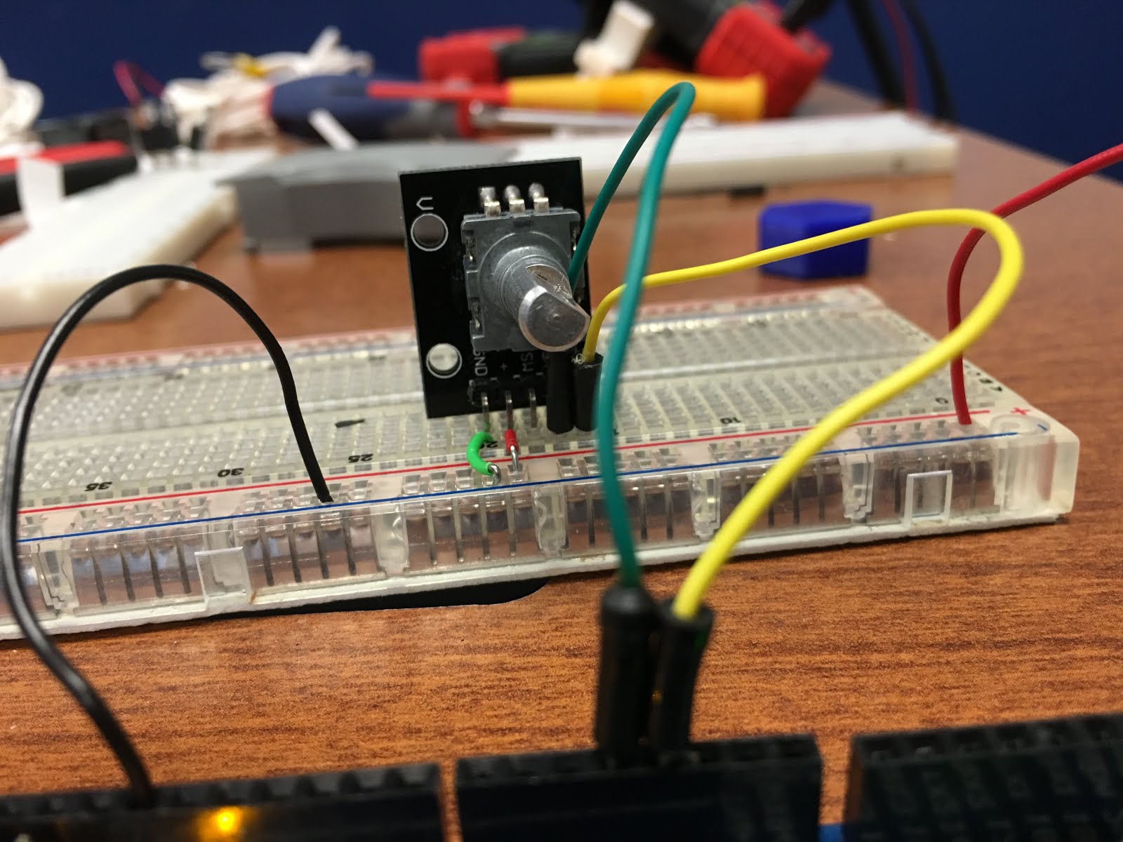
Second, wire the encoder to the arduino board. GND and + (+5V) are trivial. CLK (A) and DT (B) are next on the list, in the code above, and the working Simulink model, these pins go into Digital 3 and 4, respectively.
 |
| Wiring Diagram for the Arduino Mega 2560 and the Keyes KY-040 Angle Encoder. Pins from left to right: Ground, + (+5V), NO Push Button, DT (B), CLK (A). NO Stands for Normally Open |

 |
| This wiring is identical to the wiring in the diagram above. This is the same wiring as in the video link below. |
Connecting the Arduino Microcontroller to the Angle Encoding Simulink Model
Please check out either Method 1 or 2 of Step 1 of a past tutorial if you have not yet installed the Simulink Arduino Support Package.
If you have installed the support package but have not correctly set up the model so that you can run the model on your specific board for your desired time please see Step 2 parts: 2 (Creating an Arduino Environment in Simulink) and 3 (Creating a Simulink Block to Command the Microcontroller). Parts are bolded and contain normal font numbers below them, use ctrl+f to find the specific part you need, the () above have the titles within.
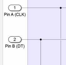 |
| View within the subsystem showing the inputs of the subsystem. An arduino, or any microcontroller, connection must be made here. The use of a subsystem here is useful so that the working block cannot be altered accidently. |
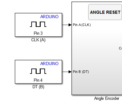
Let us now connect the missing pieces to the Simulink model, they are the CLK (A) and DT (B) of the encoder.
To connect to a Digital Pin for Input follow this: Library Browser > Simulink Support Package for Arduino Hardware > Common
From within the Common section click and drag
the Digital Input onto the model.

This next step is important for reading accuracy, latency and synchronization.
The arduino must be read in at a quick enough rate so that the encoder is as up to date as possible. The fastest an arduino, with Simulink, can read is information that can be found on the MathWorks site. The setting that the current working model for the VIPER Radio Telescope is 0.01 s, 1/100th of a second.
This is relatively slow, however, the encoder is not spinning that fast where concern for skipping is relevant. An encoder with more cycles per revolution may require quicker read in times from the arduino.
Both CLK (A) and DT (B) pins must have the same read time.
To finish off connect a DISPLAY block to the 'Current Angle' output of the subsystem created. You may notice there is an Angle Reset button, it is not necessary but useful. Explore the wonderful world of Simulink to see how to make one and use it.
Using it in the Laboratory Setting
MUST LOOK AT:A previous blog contains a how to for setting up the brakes and Pulse Width Modulation (PWM) for controlling the motor speed.
To apply this Simulink Model to the motor itself a major improvement must be made. That is, the addition to motor control based off of the angle error.
Please continue to the next blog.
Using it in the Field Setting
Find grass and use as if in the laboratory.
But in all seriousness, be careful climbing the telescope to plug the cable into the mounted encoder. If the encoder is not mounted, mount it. The cable has a label on it, use your brain.
To mount: fasten the encoder to the plastic guide, push the encoder into the 1:1 drive, slide the aluminum pins through the plastic guide and then fasten those to the horizontal aluminum plate. If you force anything, it may break the plastic due to weathering.
The aluminum plate may be very hot during mid-day. But it is the winter, YOU ARE WORKING ON SOMETHING THAT CONCENTRATES THE SUN'S RAYS!!!!!!!!
Also, above section for further instruction.
Enjoyed reading the article above, really explains everything in detail, the article is very interesting and effective. Thank you and good luck in the upcoming articles
ReplyDeletenice article, waiting for your another :)
rotary encoder