https://www.blogger.com/blogger.g?blogID=2480674472934600730#allposts
Thursday, July 13, 2017
Thursday, April 27, 2017
Tuesday, July 26, 2016
Simulink Angle Encoder Feedback Motor Control
This is a continuation of the MATLAB and Simulink Incremental Rotary Angle Encoder post.
Controlling an Elevation Motor based off of Angle Error
This is where the fun starts.
Wednesday, July 20, 2016
MATLAB and Simulink Incremental Rotary Angle Encoder
VIPER Angle Encoding System
Purpose:
To accurately read an angle encoding device that can be fixed to the 2-m Radio Telescope. Using MATLAB Simulink, an arduino microcontroller and a Keyes KY-040 Rotary Encoder module to determine the elevation angle, in both the laboratory and field settings. Additionally, establish a procedure for operation of the model in both settings.Background:
Accurately pointing the 2-m Radio Telescope is the most important function of VIPER's controlling system. To do so an Incremental Rotary Encoder is being implemented to read changes in the current angle of the telescope. To familiarize yourself with an Incremental Rotary Encoder click here and for Gray Coding click here; this device is currently being used on the VIPER Radio Telescope. The arduino code from the above link is not a precise code, as its purpose is to introduce the user to the encoder.What This Blog Accomplishes:
A explanation of how this model works, including the MATLAB Function, and how to use it in both the laboratory and field setting.
 |
| Using MATLAB Simulink, a microcontroller, and an Incremental Rotary Encoder angle changes can be detected and recorded. To do so two inputs are required to detect these changes (the CLK and DT of the encoder). With these two inputs and the application of the proper Simulink functions a precise angle encoder can be modeled and implemented. |
Simulinks Blocks Used:
 |
| Simulink Display Block |
Friday, June 24, 2016
Viper Single Motor Simulink Control
Please Check Click Here for the Latest Release of the VIPER Blog
Day 19 June 16th, 2016
This entry will show the basic setup to run the Viper Telescope motors using Simulink, a microcontroller and the power supply units. Below is the end code for one of the motors. By the end of this blog one should be able to create a running model that allows complete operation of the DC Motors that are installed onto the telescope. |
| Completed Model: This is the simulink block to control one of the brake and motor combinations of the Viper Telescope. This Simulink code ran on an Arduino Mega microcontroller which facilitated the communication between the power supplies and the operator (Simulink user). |
1. Arduino Support Simulink INSTALL
2. Motor Control Overview, Simulink/Microcontroller
Friday, June 17, 2016
Controlling Viper Overview
Day 19
6/16
We were able to control the Viper telescope's motor brake, motor direction, and motor speed by using Simulink, Arduinos, relays, an Agilent Technologies N5748A DC Power Supply, and a DCR 150-6B Power Supply.
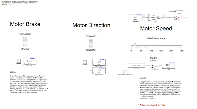
Above is the Simulink code that was used in real time to control Viper.
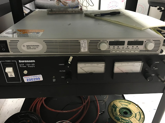
These are the two power supplies that enabled us to control Viper.
Monday, June 13, 2016
CAD to Solidworks Conversion
Day 15
6/13
The CAD files for Viper need to be converted to Solidworks in order to create the scale model. I reproduced the Ball Nut Spacer (part number 3367-A) and the Shaft/Rotor Clamp (part number 3430-2) in Solidworks. They are shown below respectively:


6/13
The CAD files for Viper need to be converted to Solidworks in order to create the scale model. I reproduced the Ball Nut Spacer (part number 3367-A) and the Shaft/Rotor Clamp (part number 3430-2) in Solidworks. They are shown below respectively:


Subscribe to:
Comments (Atom)