Friday, June 24, 2016
Viper Single Motor Simulink Control
Please Check Click Here for the Latest Release of the VIPER Blog
Friday, June 17, 2016
Controlling Viper Overview
Day 19
6/16
We were able to control the Viper telescope's motor brake, motor direction, and motor speed by using Simulink, Arduinos, relays, an Agilent Technologies N5748A DC Power Supply, and a DCR 150-6B Power Supply.

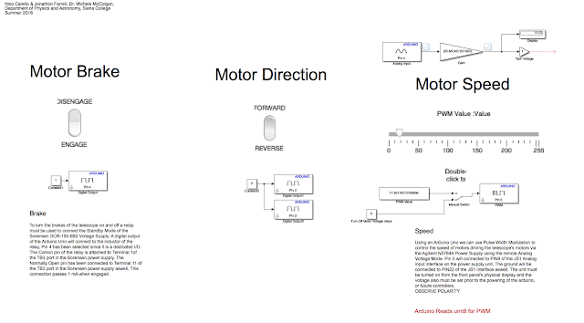
Above is the Simulink code that was used in real time to control Viper.

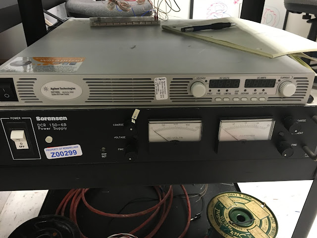
These are the two power supplies that enabled us to control Viper.
6/16
We were able to control the Viper telescope's motor brake, motor direction, and motor speed by using Simulink, Arduinos, relays, an Agilent Technologies N5748A DC Power Supply, and a DCR 150-6B Power Supply.

Above is the Simulink code that was used in real time to control Viper.

These are the two power supplies that enabled us to control Viper.
Monday, June 13, 2016
CAD to Solidworks Conversion
creating an inductor, resistor and capacitor tester
last week I found a inductance tester online to build using an LCD and arduino mega board, and a 393 op amp. After some research it was decided i would make all three testers on the arduino board and display them on a LCD the websites I used are listed below
393 op amp datasheet
inductance tester circuit design
code for inductance tester
schematic and code for resistance meter
circuit design and code for capacitor tester
all three circuits are working on the same arduino mega, but they each need different code depending on what is being tested as all three codes cannot run on an arduino at one time.
Thursday, June 9, 2016
Model Viper Encoder Attachment
Tuesday, June 7, 2016
Field Trip
Day 10
6/6
In order to complete the Micro Controlled Power Supply we needed a 680uH Inductor. We called Trojan Electronic Supply located at Middleburgh and 8th street in Troy to see if they had the inductor we needed.

Upon arrival, the store did have the inductor we needed and cost one whole dollar. The store is pictured below:

6/6
In order to complete the Micro Controlled Power Supply we needed a 680uH Inductor. We called Trojan Electronic Supply located at Middleburgh and 8th street in Troy to see if they had the inductor we needed.

Upon arrival, the store did have the inductor we needed and cost one whole dollar. The store is pictured below:

Friday, June 3, 2016
Scale Model of Viper
Day 9
6/3
On Day 8 I took pictures of Viper and began to sketch the telescope on a white board in order to refer back to it when I replicate it in Solidworks. The original sketch with some information is below:
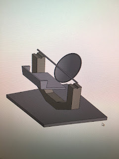
The morning of Day 9 I went through various tutorials to learn how to use Solidworks. After completing several tutorials I started on the model of Viper. The base plate, the arm where the encoder will go, and the dish were completed.

The rest of the day was spent creating some additional pieces as well as placing them in a similar position to where they will be on the model:

6/3
On Day 8 I took pictures of Viper and began to sketch the telescope on a white board in order to refer back to it when I replicate it in Solidworks. The original sketch with some information is below:

The morning of Day 9 I went through various tutorials to learn how to use Solidworks. After completing several tutorials I started on the model of Viper. The base plate, the arm where the encoder will go, and the dish were completed.

The rest of the day was spent creating some additional pieces as well as placing them in a similar position to where they will be on the model:

Thursday, June 2, 2016
Arduino IDE analogWrite (MatLAB: writePWMVoltage)
June 2nd, 2016 --- Day 8
MATLAB has an analogWrite() parallel, writePWMVoltage().
The main goal was to control the voltage of an output pin to dim an LED or to change the speed of a DC motor. The following is arduino code that runs in an Arduino IDE
--------------------------------------------------------------------------------------------------------------------------
// Control voltage out of PWM Digital pins using analogWrite(PIN,value[0 to 255]) function
int motorPin = 3; // DC Motor is on digital Pin 3, PWM pin
int val = 0; // variable to store current value
void setup()
{
pinMode(motorPin, OUTPUT); // Declare this pin as an output
Serial.begin(9600); // set up Serial library at 9600 bps
}
void loop()
{
// motor operates well between 180 and 255 for duty cycle values
for(int motorValue = 180 ; motorValue <= 255; motorValue +=1){ // If motor is at 130 turn up until 255 is reached
analogWrite(motorPin, motorValue); // Write to motorPin the value motorValue
delay(1000); // .1 second delay
Serial.println(motorValue);
}
for(int motorValue = 255 ; motorValue >= 180; motorValue -=1){ //set conditions
analogWrite(motorPin, motorValue); // turn motor
delay(1000); // .1 second delay
Serial.println(motorValue);
}
}
--------------------------------------------------------------------------------------------------------------------------
The MATLAB Arduino Support Package has a replica feature called 'writePWMVoltage' which was realized as pins were declared in the Arduino IDE. The difference is that the arduino to be channelled must be acknowledged within the function within the MatLAB code. The syntax is writePWMVoltage(arduino,'pin',voltage), the pin must be entered in as a string and the voltage is a range between 0 and 5 in intervals of 256.
Arduino Support Package for MATLAB 2
Day 8
6/2
Today we downloaded the Arduino Support Package for MATLAB. We went into the help documentation area of MATLAB to learn more about how MATLAB works with the Arduino. This documentation provided several pages we found useful. Below is an example of one of those pages titled write digital pin:

We printed out around twenty similar pages we found useful and placed them neatly into a binder for future reference.

6/2
Today we downloaded the Arduino Support Package for MATLAB. We went into the help documentation area of MATLAB to learn more about how MATLAB works with the Arduino. This documentation provided several pages we found useful. Below is an example of one of those pages titled write digital pin:

We printed out around twenty similar pages we found useful and placed them neatly into a binder for future reference.

measuring inductors
Day 7
june 2, 2016
These past few days have been spent measuring the inductance value of some inductors we found, as the circuit we are making requires a 680 micro henry inductor, after using the first method off of the wikihow website I tested a little more than half of the old inductors I found to find that none of them were 680 microHenry, while we wait for the mosfet to come in from being ordered we will keep looking for a inductor in our range in the meantime we have been helping to clean and organize the gen phys room.
Wednesday, June 1, 2016
Arduino Support Package for MATLAB 1
June 1st, 2nd - Day 7,8
The tutorial video linked here uses the Arduino Support Package for MatLAB, not the same as the SIMULINK support package. If the line of code --- a = arduino('comPort','UNO') --- is ran in the Command Window or a script you will be prompted to download the support package. When installing this package you will be prompted to select the download for example codes, do so, as they are useful.
http://www.mathworks.com/hardware-support/arduino-matlab.html
 |
| MatLAB lacks the ability to write to an analog pin. The Arduino IDE will be employed to use this feature of the board. |
Micro Controlled Power Supply 2
Day 6
5/31
Continued to work on the Micro Controlled Power Supply. The mosfet we need is still not in stock but has been ordered. We tested resistances with a Innova 3320 Multimeter to make sure they give the desired resistance values, since some are quite aged. This is the current state of the circuit:

5/31
Continued to work on the Micro Controlled Power Supply. The mosfet we need is still not in stock but has been ordered. We tested resistances with a Innova 3320 Multimeter to make sure they give the desired resistance values, since some are quite aged. This is the current state of the circuit:

Subscribe to:
Comments (Atom)


