https://www.blogger.com/blogger.g?blogID=2480674472934600730#allposts
Thursday, July 13, 2017

Thursday, April 27, 2017
Tuesday, July 26, 2016
Simulink Angle Encoder Feedback Motor Control
This is a continuation of the MATLAB and Simulink Incremental Rotary Angle Encoder post.
Controlling an Elevation Motor based off of Angle Error
This is where the fun starts.
Wednesday, July 20, 2016
MATLAB and Simulink Incremental Rotary Angle Encoder
VIPER Angle Encoding System
Purpose:
To accurately read an angle encoding device that can be fixed to the 2-m Radio Telescope. Using MATLAB Simulink, an arduino microcontroller and a Keyes KY-040 Rotary Encoder module to determine the elevation angle, in both the laboratory and field settings. Additionally, establish a procedure for operation of the model in both settings.Background:
Accurately pointing the 2-m Radio Telescope is the most important function of VIPER's controlling system. To do so an Incremental Rotary Encoder is being implemented to read changes in the current angle of the telescope. To familiarize yourself with an Incremental Rotary Encoder click here and for Gray Coding click here; this device is currently being used on the VIPER Radio Telescope. The arduino code from the above link is not a precise code, as its purpose is to introduce the user to the encoder.What This Blog Accomplishes:
A explanation of how this model works, including the MATLAB Function, and how to use it in both the laboratory and field setting.
 |
| Using MATLAB Simulink, a microcontroller, and an Incremental Rotary Encoder angle changes can be detected and recorded. To do so two inputs are required to detect these changes (the CLK and DT of the encoder). With these two inputs and the application of the proper Simulink functions a precise angle encoder can be modeled and implemented. |
Simulinks Blocks Used:
 |
| Simulink Display Block |
Friday, June 24, 2016
Viper Single Motor Simulink Control
Please Check Click Here for the Latest Release of the VIPER Blog
Day 19 June 16th, 2016
This entry will show the basic setup to run the Viper Telescope motors using Simulink, a microcontroller and the power supply units. Below is the end code for one of the motors. By the end of this blog one should be able to create a running model that allows complete operation of the DC Motors that are installed onto the telescope. |
| Completed Model: This is the simulink block to control one of the brake and motor combinations of the Viper Telescope. This Simulink code ran on an Arduino Mega microcontroller which facilitated the communication between the power supplies and the operator (Simulink user). |
1. Arduino Support Simulink INSTALL
2. Motor Control Overview, Simulink/Microcontroller
Friday, June 17, 2016
Controlling Viper Overview
Day 19
6/16
We were able to control the Viper telescope's motor brake, motor direction, and motor speed by using Simulink, Arduinos, relays, an Agilent Technologies N5748A DC Power Supply, and a DCR 150-6B Power Supply.
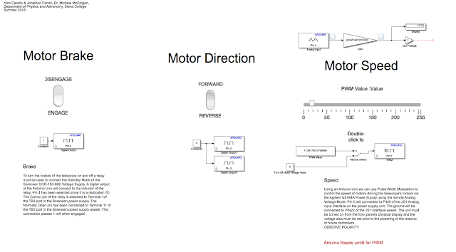
Above is the Simulink code that was used in real time to control Viper.
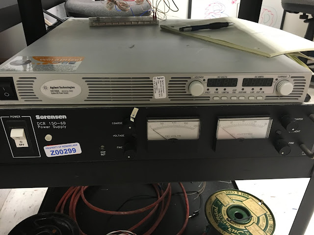
These are the two power supplies that enabled us to control Viper.
6/16
We were able to control the Viper telescope's motor brake, motor direction, and motor speed by using Simulink, Arduinos, relays, an Agilent Technologies N5748A DC Power Supply, and a DCR 150-6B Power Supply.

Above is the Simulink code that was used in real time to control Viper.

These are the two power supplies that enabled us to control Viper.
Monday, June 13, 2016
CAD to Solidworks Conversion
Day 15
6/13
The CAD files for Viper need to be converted to Solidworks in order to create the scale model. I reproduced the Ball Nut Spacer (part number 3367-A) and the Shaft/Rotor Clamp (part number 3430-2) in Solidworks. They are shown below respectively:


6/13
The CAD files for Viper need to be converted to Solidworks in order to create the scale model. I reproduced the Ball Nut Spacer (part number 3367-A) and the Shaft/Rotor Clamp (part number 3430-2) in Solidworks. They are shown below respectively:


creating an inductor, resistor and capacitor tester
last week I found a inductance tester online to build using an LCD and arduino mega board, and a 393 op amp. After some research it was decided i would make all three testers on the arduino board and display them on a LCD the websites I used are listed below
393 op amp datasheet
inductance tester circuit design
code for inductance tester
schematic and code for resistance meter
circuit design and code for capacitor tester
all three circuits are working on the same arduino mega, but they each need different code depending on what is being tested as all three codes cannot run on an arduino at one time.
393 op amp datasheet
inductance tester circuit design
code for inductance tester
schematic and code for resistance meter
circuit design and code for capacitor tester
all three circuits are working on the same arduino mega, but they each need different code depending on what is being tested as all three codes cannot run on an arduino at one time.
Thursday, June 9, 2016
Model Viper Encoder Attachment
Day 12
6/8
The goal was to 3D print an object that would allow the encoder to be attached to the 3D model of Viper. The design was quite simple: a circle with a 'D' cut out of the middle to allow the encoder to be attached.


6/8
The goal was to 3D print an object that would allow the encoder to be attached to the 3D model of Viper. The design was quite simple: a circle with a 'D' cut out of the middle to allow the encoder to be attached.


Tuesday, June 7, 2016
Field Trip
Day 10
6/6
In order to complete the Micro Controlled Power Supply we needed a 680uH Inductor. We called Trojan Electronic Supply located at Middleburgh and 8th street in Troy to see if they had the inductor we needed.

Upon arrival, the store did have the inductor we needed and cost one whole dollar. The store is pictured below:

6/6
In order to complete the Micro Controlled Power Supply we needed a 680uH Inductor. We called Trojan Electronic Supply located at Middleburgh and 8th street in Troy to see if they had the inductor we needed.

Upon arrival, the store did have the inductor we needed and cost one whole dollar. The store is pictured below:

Friday, June 3, 2016
Scale Model of Viper
Day 9
6/3
On Day 8 I took pictures of Viper and began to sketch the telescope on a white board in order to refer back to it when I replicate it in Solidworks. The original sketch with some information is below:
The morning of Day 9 I went through various tutorials to learn how to use Solidworks. After completing several tutorials I started on the model of Viper. The base plate, the arm where the encoder will go, and the dish were completed.

The rest of the day was spent creating some additional pieces as well as placing them in a similar position to where they will be on the model:
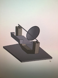
6/3
On Day 8 I took pictures of Viper and began to sketch the telescope on a white board in order to refer back to it when I replicate it in Solidworks. The original sketch with some information is below:

The morning of Day 9 I went through various tutorials to learn how to use Solidworks. After completing several tutorials I started on the model of Viper. The base plate, the arm where the encoder will go, and the dish were completed.

The rest of the day was spent creating some additional pieces as well as placing them in a similar position to where they will be on the model:

Thursday, June 2, 2016
Arduino IDE analogWrite (MatLAB: writePWMVoltage)
June 2nd, 2016 --- Day 8
MATLAB has an analogWrite() parallel, writePWMVoltage().
The main goal was to control the voltage of an output pin to dim an LED or to change the speed of a DC motor. The following is arduino code that runs in an Arduino IDE
--------------------------------------------------------------------------------------------------------------------------
// Control voltage out of PWM Digital pins using analogWrite(PIN,value[0 to 255]) function
int motorPin = 3; // DC Motor is on digital Pin 3, PWM pin
int val = 0; // variable to store current value
void setup()
{
pinMode(motorPin, OUTPUT); // Declare this pin as an output
Serial.begin(9600); // set up Serial library at 9600 bps
}
void loop()
{
// motor operates well between 180 and 255 for duty cycle values
for(int motorValue = 180 ; motorValue <= 255; motorValue +=1){ // If motor is at 130 turn up until 255 is reached
analogWrite(motorPin, motorValue); // Write to motorPin the value motorValue
delay(1000); // .1 second delay
Serial.println(motorValue);
}
for(int motorValue = 255 ; motorValue >= 180; motorValue -=1){ //set conditions
analogWrite(motorPin, motorValue); // turn motor
delay(1000); // .1 second delay
Serial.println(motorValue);
}
}
MATLAB has an analogWrite() parallel, writePWMVoltage().
The main goal was to control the voltage of an output pin to dim an LED or to change the speed of a DC motor. The following is arduino code that runs in an Arduino IDE
--------------------------------------------------------------------------------------------------------------------------
// Control voltage out of PWM Digital pins using analogWrite(PIN,value[0 to 255]) function
int motorPin = 3; // DC Motor is on digital Pin 3, PWM pin
int val = 0; // variable to store current value
void setup()
{
pinMode(motorPin, OUTPUT); // Declare this pin as an output
Serial.begin(9600); // set up Serial library at 9600 bps
}
void loop()
{
// motor operates well between 180 and 255 for duty cycle values
for(int motorValue = 180 ; motorValue <= 255; motorValue +=1){ // If motor is at 130 turn up until 255 is reached
analogWrite(motorPin, motorValue); // Write to motorPin the value motorValue
delay(1000); // .1 second delay
Serial.println(motorValue);
}
for(int motorValue = 255 ; motorValue >= 180; motorValue -=1){ //set conditions
analogWrite(motorPin, motorValue); // turn motor
delay(1000); // .1 second delay
Serial.println(motorValue);
}
}
--------------------------------------------------------------------------------------------------------------------------
The MATLAB Arduino Support Package has a replica feature called 'writePWMVoltage' which was realized as pins were declared in the Arduino IDE. The difference is that the arduino to be channelled must be acknowledged within the function within the MatLAB code. The syntax is writePWMVoltage(arduino,'pin',voltage), the pin must be entered in as a string and the voltage is a range between 0 and 5 in intervals of 256.
Arduino Support Package for MATLAB 2
Day 8
6/2
Today we downloaded the Arduino Support Package for MATLAB. We went into the help documentation area of MATLAB to learn more about how MATLAB works with the Arduino. This documentation provided several pages we found useful. Below is an example of one of those pages titled write digital pin:

We printed out around twenty similar pages we found useful and placed them neatly into a binder for future reference.

6/2
Today we downloaded the Arduino Support Package for MATLAB. We went into the help documentation area of MATLAB to learn more about how MATLAB works with the Arduino. This documentation provided several pages we found useful. Below is an example of one of those pages titled write digital pin:

We printed out around twenty similar pages we found useful and placed them neatly into a binder for future reference.

measuring inductors
Day 7
june 2, 2016
These past few days have been spent measuring the inductance value of some inductors we found, as the circuit we are making requires a 680 micro henry inductor, after using the first method off of the wikihow website I tested a little more than half of the old inductors I found to find that none of them were 680 microHenry, while we wait for the mosfet to come in from being ordered we will keep looking for a inductor in our range in the meantime we have been helping to clean and organize the gen phys room.
june 2, 2016
These past few days have been spent measuring the inductance value of some inductors we found, as the circuit we are making requires a 680 micro henry inductor, after using the first method off of the wikihow website I tested a little more than half of the old inductors I found to find that none of them were 680 microHenry, while we wait for the mosfet to come in from being ordered we will keep looking for a inductor in our range in the meantime we have been helping to clean and organize the gen phys room.
Wednesday, June 1, 2016
Arduino Support Package for MATLAB 1
June 1st, 2nd - Day 7,8
The tutorial video linked here uses the Arduino Support Package for MatLAB, not the same as the SIMULINK support package. If the line of code --- a = arduino('comPort','UNO') --- is ran in the Command Window or a script you will be prompted to download the support package. When installing this package you will be prompted to select the download for example codes, do so, as they are useful.
http://www.mathworks.com/hardware-support/arduino-matlab.html
The tutorial video linked here uses the Arduino Support Package for MatLAB, not the same as the SIMULINK support package. If the line of code --- a = arduino('comPort','UNO') --- is ran in the Command Window or a script you will be prompted to download the support package. When installing this package you will be prompted to select the download for example codes, do so, as they are useful.
http://www.mathworks.com/hardware-support/arduino-matlab.html
 |
| This is the resulting command line after running the script shown in the editor. The first run will result in the 'Update' of the code on the board, this will run for half a minute or so. Once completed it will run the function as intended, printing the 'a =' statement. |
 |
| MatLAB lacks the ability to write to an analog pin. The Arduino IDE will be employed to use this feature of the board. |
Micro Controlled Power Supply 2
Day 6
5/31
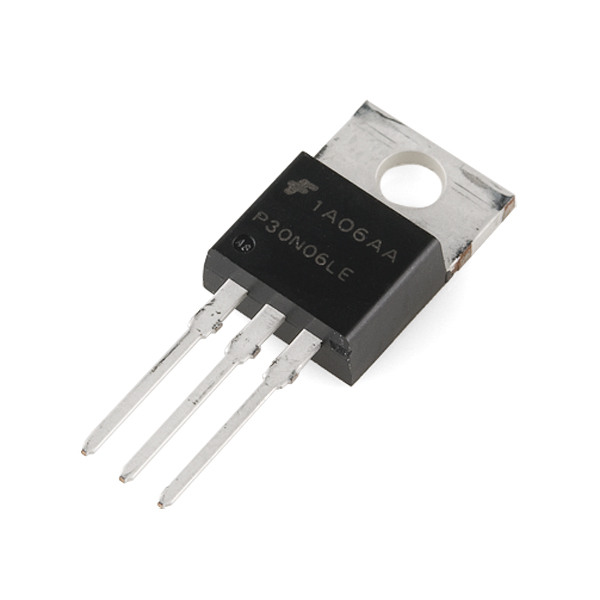
Continued to work on the Micro Controlled Power Supply. The mosfet we need is still not in stock but has been ordered. We tested resistances with a Innova 3320 Multimeter to make sure they give the desired resistance values, since some are quite aged. This is the current state of the circuit:

5/31
Continued to work on the Micro Controlled Power Supply. The mosfet we need is still not in stock but has been ordered. We tested resistances with a Innova 3320 Multimeter to make sure they give the desired resistance values, since some are quite aged. This is the current state of the circuit:

Tuesday, May 31, 2016
Arduino to MATLAB Serial Communication
Please Check Click Here for the Latest Release of the VIPER Blog
31 May 2016
For the VIPER Radio Telescope an angle (angel) encoder is being used to determine the angle at which the telescope is at any point in time. For this we are currently using the Keyes KY-040 Arduino Rotary Encoder on an Arduino Uno using the Arduino IDE to code for rotation from this site, which shows exactly how to wire, upload, quite literally everything. This was found on Mike's blogs that he had directed me to, thanks Mike.
--------------------------------------------------------------------------------------------------------------------------
------------------------------------ ANGLE ENCODER ARDUINO CODE ------------------------------------
--------------------------------------------------------------------------------------------------------------------------
NOTE: The following code is directly copied from the website linked above. This is the code for the NON-PUSHBUTTON because we will reset the counter via the Zedboard when that is necessary.
--------------------------------------------------------------------------------------------------------------------------
//From bildr article: http://bildr.org/2012/08/rotary-encoder-arduino/
//these pins can not be changed 2/3 are special pins
int encoderPin1 = 2;
int encoderPin2 = 3;
volatile int lastEncoded = 0;
volatile long encoderValue = 0;
long lastencoderValue = 0;
int lastMSB = 0;
int lastLSB = 0;
void setup() {
Serial.begin (9600);
pinMode(encoderPin1, INPUT);
pinMode(encoderPin2, INPUT);
digitalWrite(encoderPin1, HIGH); //turn pullup resistor on
digitalWrite(encoderPin2, HIGH); //turn pullup resistor on
//call updateEncoder() when any high/low changed seen
//on interrupt 0 (pin 2), or interrupt 1 (pin 3)
attachInterrupt(0, updateEncoder, CHANGE);
attachInterrupt(1, updateEncoder, CHANGE);
}
void loop(){
//Do stuff here
Serial.println(encoderValue);
delay(1000); //just here to slow down the output, and show it will work even during a delay
}
void updateEncoder(){
int MSB = digitalRead(encoderPin1); //MSB = most significant bit
int LSB = digitalRead(encoderPin2); //LSB = least significant bit
int encoded = (MSB << 1) |LSB; //converting the 2 pin value to single number
int sum = (lastEncoded << 2) | encoded; //adding it to the previous encoded value
if(sum == 0b1101 || sum == 0b0100 || sum == 0b0010 || sum == 0b1011) encoderValue ++;
if(sum == 0b1110 || sum == 0b0111 || sum == 0b0001 || sum == 0b1000) encoderValue --;
lastEncoded = encoded; //store this value for next time
}
--------------------------------------------------------------------------------------------------------------------------
The only edit that was made to the code employed in the working model is riding the code of the delay(1000); entirely, so that the code will spit out the current value as fast as it can.
To start the small scale testing the serial monitor of the Arduino IDE was used as a check. These values changed at increments of 1 or -1 depending upon rotation and the wiring of the CLK and DT pins.

Here it goes from 2 to 3, and so on. Initially when I started running the first bits were 0, this must be 0 at the start. You can also get the EXACT location on the computer of the serial feed (COM PORT). In my case the serial feed is "/dev/cu.usbmodem1411". When this address (COM PORT) is entered into MATLAB it will be changed slightly to ('/dev/tty.usbmodem1411'). In MATLAB the ' ' must go around the location of your COM PORT.
The Arduino side is working, did someone say MATLAB? Matlab.
Reading serial data into MATLAB is quite simple, once every forum has been sifted through. I will do my best to be as thorough as possible.
links used:
Locating COM PORT PC/MAC/LINUX
fgets fclose fopen
ArduinoMatlab.org/serial MORE USEFUL VIDEO
Connecting Arduino to a Mac for Serial to Matlab
First I will directly past the working code, it is not perfect, but it currently what is needed.
--------------------------------------------------------------------------------------------------------------------------
--------------------------------------------------------------------------------------------------------------------------
Future work.
1. Connect to a PID controller to regulate a motor that will spin something that this encoder measures.
2. Using a planetary gear system create a ratio that is useful to scientists. For example: if 1/10th of a degree is useful to these folks make a gear ratio of 10 to 1, (encoder to Viper Journal Bearing Mount)
It includes a MATLAB Simulink tutorial for the Incremental Rotary Encoder using the Keyes KY-040 module.
31 May 2016
For the VIPER Radio Telescope an angle (angel) encoder is being used to determine the angle at which the telescope is at any point in time. For this we are currently using the Keyes KY-040 Arduino Rotary Encoder on an Arduino Uno using the Arduino IDE to code for rotation from this site, which shows exactly how to wire, upload, quite literally everything. This was found on Mike's blogs that he had directed me to, thanks Mike.
--------------------------------------------------------------------------------------------------------------------------
------------------------------------ ANGLE ENCODER ARDUINO CODE ------------------------------------
--------------------------------------------------------------------------------------------------------------------------
NOTE: The following code is directly copied from the website linked above. This is the code for the NON-PUSHBUTTON because we will reset the counter via the Zedboard when that is necessary.
--------------------------------------------------------------------------------------------------------------------------
//From bildr article: http://bildr.org/2012/08/rotary-encoder-arduino/
//these pins can not be changed 2/3 are special pins
int encoderPin1 = 2;
int encoderPin2 = 3;
volatile int lastEncoded = 0;
volatile long encoderValue = 0;
long lastencoderValue = 0;
int lastMSB = 0;
int lastLSB = 0;
void setup() {
Serial.begin (9600);
pinMode(encoderPin1, INPUT);
pinMode(encoderPin2, INPUT);
digitalWrite(encoderPin1, HIGH); //turn pullup resistor on
digitalWrite(encoderPin2, HIGH); //turn pullup resistor on
//call updateEncoder() when any high/low changed seen
//on interrupt 0 (pin 2), or interrupt 1 (pin 3)
attachInterrupt(0, updateEncoder, CHANGE);
attachInterrupt(1, updateEncoder, CHANGE);
}
void loop(){
//Do stuff here
Serial.println(encoderValue);
delay(1000); //just here to slow down the output, and show it will work even during a delay
}
void updateEncoder(){
int MSB = digitalRead(encoderPin1); //MSB = most significant bit
int LSB = digitalRead(encoderPin2); //LSB = least significant bit
int encoded = (MSB << 1) |LSB; //converting the 2 pin value to single number
int sum = (lastEncoded << 2) | encoded; //adding it to the previous encoded value
if(sum == 0b1101 || sum == 0b0100 || sum == 0b0010 || sum == 0b1011) encoderValue ++;
if(sum == 0b1110 || sum == 0b0111 || sum == 0b0001 || sum == 0b1000) encoderValue --;
lastEncoded = encoded; //store this value for next time
}
--------------------------------------------------------------------------------------------------------------------------
The only edit that was made to the code employed in the working model is riding the code of the delay(1000); entirely, so that the code will spit out the current value as fast as it can.
To start the small scale testing the serial monitor of the Arduino IDE was used as a check. These values changed at increments of 1 or -1 depending upon rotation and the wiring of the CLK and DT pins.
Here it goes from 2 to 3, and so on. Initially when I started running the first bits were 0, this must be 0 at the start. You can also get the EXACT location on the computer of the serial feed (COM PORT). In my case the serial feed is "/dev/cu.usbmodem1411". When this address (COM PORT) is entered into MATLAB it will be changed slightly to ('/dev/tty.usbmodem1411'). In MATLAB the ' ' must go around the location of your COM PORT.
The Arduino side is working, did someone say MATLAB? Matlab.
Reading serial data into MATLAB is quite simple, once every forum has been sifted through. I will do my best to be as thorough as possible.
links used:
Locating COM PORT PC/MAC/LINUX
fgets fclose fopen
ArduinoMatlab.org/serial MORE USEFUL VIDEO
Connecting Arduino to a Mac for Serial to Matlab
First I will directly past the working code, it is not perfect, but it currently what is needed.
--------------------------------------------------------------------------------------------------------------------------
--------------------------------------Matlab Serial Reading for Angle Encoder----------------------------------
--------------------------------------------------------------------------------------------------------------------------
% Date: 31 May 2016
% Start serial communication between an Arduino and MatLAB.
% If setup is complete the arduino will output a 1, else a 0.
%% SET CONDITIONS for MatLAB to read in ARDUINO SERIAL CHARACTER OUTPUT
s = serial('/dev/tty.usbmodem1411'); % Set com location, this is for a Mac
set(s,'DataBits',8); % Set to same values on Arduino, can be found at arduino.cc
set(s,'StopBits',1);
set(s,'BaudRate',9600); % important, needed, double check for this error
set(s,'Parity','none');
% This can also be entered in in one (1) line as follows:
% s = serial('/dev/tty.usbmodem1411','DataBits',8,'StopBits',1,'BaudRate',9600,'Parity','none');
%% Open the connection to MatLAB
fopen(s); % connects serial object 's' to the arduino
%% Using an infinite loop read (GET) the INFORMATION that is RELEVANT
while (1==1)
fgets(s) % Use a ';' if you want this info to not be seen this is the
% information that it is wanted for the Angel Encoder.
% This will returned IDENTICAL to that of the Arduino IDE
% serial output.
end
 |
| If you find that to end your code you must close MATLAB down entirely check out this quick video that was made to get around the horror of restarting MATLAB. |
Future work.
1. Connect to a PID controller to regulate a motor that will spin something that this encoder measures.
2. Using a planetary gear system create a ratio that is useful to scientists. For example: if 1/10th of a degree is useful to these folks make a gear ratio of 10 to 1, (encoder to Viper Journal Bearing Mount)
Friday, May 27, 2016
Micro Controlled Power Supply 1
Day 5
5/27
We were tasked with making a micro controlled power supply in order to control the speed of our motor. To do this we need one 22uF capacitor, two 1000uF capacitors, one inductor, one 10k resistor, two 100k resistors, two diodes, and an Opamp. We set up the micro controlled power supply in a circuit but were unable to complete it because some items were not in stock.
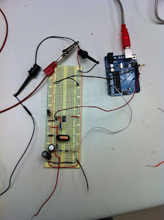
The above picture is what the final product will look like.
5/27
We were tasked with making a micro controlled power supply in order to control the speed of our motor. To do this we need one 22uF capacitor, two 1000uF capacitors, one inductor, one 10k resistor, two 100k resistors, two diodes, and an Opamp. We set up the micro controlled power supply in a circuit but were unable to complete it because some items were not in stock.

The above picture is what the final product will look like.
Thursday, May 26, 2016
Arduino Mega 2560 NOT CAPABLE of Analog Output
Day 4
May 26th, 2016
We found the only Arduino capable, with Simulink, of Analog Output is the Due. With that,
the Leader 718-3D Power Supply was not remotely tunable as hoped. So, it is not completely terrible that our progress was cut short in the beginning.
We are looking into controlling a GPIB with Simulink and possibly the Mega 2560 that we have or a Zed Board.
May 26th, 2016
We found the only Arduino capable, with Simulink, of Analog Output is the Due. With that,
the Leader 718-3D Power Supply was not remotely tunable as hoped. So, it is not completely terrible that our progress was cut short in the beginning.
We are looking into controlling a GPIB with Simulink and possibly the Mega 2560 that we have or a Zed Board.
Controlling Motor Directional and On/Off power with Relay
Day 4
May 26th, 2016
To have further control of the motors we decided to integrate the CCW and CW JZC-11F Relay circuits into a Simulink diagram. We were successfully able to control the relays, with minimal issues, directly from the Arduino Mega 2560. The hard circuit was on a proto-board, where we used the power from that for the external loads.

Simulink Panel: The switches were linked to the respective constant values that would either release a 1 or 0 depending upon the action the user wanted. The outputs went to digital pins that would then turn a relay on or off performing the task it was designed to do.

Physical Hard Wiring of the circuit. The DC Motor is on the bottom between two knobs. We found that it was easiest to Turn the motor off then to switch directions.
May 26th, 2016
To have further control of the motors we decided to integrate the CCW and CW JZC-11F Relay circuits into a Simulink diagram. We were successfully able to control the relays, with minimal issues, directly from the Arduino Mega 2560. The hard circuit was on a proto-board, where we used the power from that for the external loads.

Simulink Panel: The switches were linked to the respective constant values that would either release a 1 or 0 depending upon the action the user wanted. The outputs went to digital pins that would then turn a relay on or off performing the task it was designed to do.

Physical Hard Wiring of the circuit. The DC Motor is on the bottom between two knobs. We found that it was easiest to Turn the motor off then to switch directions.
Subscribe to:
Posts (Atom)